EasyProbe - Probe software for machining centres

About EasyProbe software
EasyProbe software cycles are designed for use by machine tool operators for simple job set-up and measuring tasks on machining centres. The software can be easily configured, using a supplied install utility, to suit the machine tool configuration.
Probing can either be through use of the machine tool handwheel / jog function with cycles run via manual data input, or through cycles written into a part program and run automatically.
Features and benefits
- Simple programming - EasyProbe cycles require little programming skill to achieve simple probing tasks
- Part set-up - work offsets can be updated for accurate component positioning
- Measurement results and errors are stored in a macro variable list
- Angle find macro can be used to update a 4th axis or enable G68 co-ordinate rotation
EasyProbe specification
| Specification | |
|---|---|
| Memory requirement | 6.0 kB |
| Compatibility | Fanuc Macro B 0MB, 0MC, 6M, 10-15M, 16-21M Mitsubishi Meldas M3, M310, M320, M330, M520 Yasnac MX3, I80, J50, J300 Haas |
Probing cycles featured in the EasyProbe software
EasyProbe offers simple programming for basic workpiece set-up and part inspection tasks.
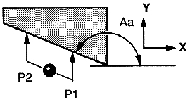
Angle measure
 The
angle of a surface can be found by running two single
surface measure routines, the second with an 'A' input
to calculate the angle between the two points.
The angle can then be used to update a 4th axis or enable G68 co-ordinate rotation.
| Example | |
|---|---|
| G65 P9023 Y10. | Y- single surface measure P1. |
| G0 G91 X-50. Y15. | Move from P1 to P2. Use either the jog or handwheel mode. |
| G65 P9023 A160. Y10. | Y- single surface P2 measure to find the angle
error. Stored in #144. |
| G68 G90 X0.R#144 | Apply rotation. |
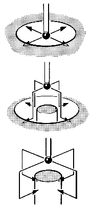
Bore / boss cycle
 This
cycle is used to measure the feature width and centre
position using four points parallel with the X and Y
axes.
The error of size and centre position can be stored or used to update the relevant work offset registers.
This cycle is also used to calibrate the XY axis offsets of a probe and the radii of a probe stylus ball.
| Example | |
|---|---|
| G65 P9023 D50. S59. I50. J50. | Set the centre at X=50, Y=50 relative to G59 X0 Y0 |
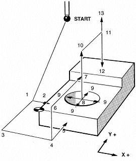
EasyProbe sample program
 Sample
program and description of all EasyProbe programming
terms.
| Example program |
|
|---|---|
| % | |
| G80 G90 G00 | |
| T01 | |
| M06 | |
| G54 X0 Y0 | |
| G43 H1 Z100. | |
| G65 P9023 M1. (Switch on probe) | |
| 1. | G65 P9770 X-10.0 Y10.0 Z-5.0 F1000 (Protected move) |
| 2. | G65 P9023 X10.0 S54 (Single surface measure, set G54 X) |
| 3. | G65 P9770 Y-10. |
| 4. | G65 P9770 X10. |
| 5. | G65 P9023 Y10. S54 (Single surface measure, set G54 Y) |
| 6. | G0 Z10. (Clearance move) |
| 7. | G65 P9770 X50. Y50. |
| 8. | G65 P9770 Z-5. |
| 9. | G65 P9023 D40. H0.2 (Bore measure) |
| 10. | G0 Z20.0 |
| 11. | G65 P9770 Y90. |
| 12. | G65 P9023 Z-20. S54. K5. (Single surface measure, set G54 Z) |
| 13. | G28 Z100. |
| M30 |
| Program inputs description | |
|---|---|
| A+/A- | Angle input for measuring an angle |
| C | Indicates a calibration cycle |
| D | The nominal size of the feature for measuring a bore/ boss or web / pocket |
| I+/I- | Required X position of the feature when setting a work offset |
| J+/J- | Required Y position of the feature when setting a work offset |
| K+/K- | Required Z position of the feature when setting a work offset |
| M | Used to control probe switching options |
| Q | Probe overtravel distance |
| R+/R- | Radial clearance between the stylus and the side of a feature. Can be negative for an internal web or boss cycle. |
| S | Work offset to be updated for position |
| X+/X- | Approximate distance and direction to X surface |
| OR | |
| X1. | Indicates measuring a web / pocket in the X axis |
| Y+/Y- | Approximate distance and direction to Y surface |
| OR | |
| Y1. | Indicates measuring a web / pocket in the Y axis |
| Z+/Z- | Approximate distance and direction to the Z surface |
![]()

